

How to Size Battery Storage for Germany's Electric Truck Depot Charging Funding
Germany's heavy-duty charging funding can help depots install electric truck chargers, but the key design question is still technical: can the site grid connection support the charging power, or does the depot need battery storage as a buffer?
For a logistics operator, charger funding does not automatically solve the grid problem. A depot may receive support for charging infrastructure and still face a transformer limit, a long grid upgrade timeline or a peak-demand cost problem. Battery storage becomes relevant when charger power is higher than the site's available grid capacity for short charging windows.
Germany's 2026 heavy-duty charging programme has moved depot charging from a future plan to a near-term engineering task. In its funding announcement, NOW GmbH describes a dedicated call for non-public heavy-duty charging infrastructure with an application window from 26 May to 7 July 2026. For logistics sites, that deadline creates urgency, but the harder question comes after the funding form: if the depot installs 100 kW, 300 kW or 400 kW chargers, can the existing grid connection actually support the charging window?
That is where battery storage enters the discussion. It should be evaluated before hardware selection, not added later as a patch for an undersized grid connection.
Start With the Power Gap, Not the Battery Size
Depot charging is a power problem before it is an energy problem.
Battery support power = Charger demand - Available grid capacity - Usable PV contribution
If the depot ignores this step, it may overspend on chargers that cannot run at full power or undersize the storage system that should support them.
Example
| Planning item | Example value |
| Charger demand | 400 kW |
| Available grid capacity | 160 kW |
| Usable PV during session | 0 kW |
| Battery support power needed | 240 kW |
Then calculate duration:
Battery energy needed = Battery support power x charging support time
| Support scenario | Calculation | Energy need |
| 30-minute support | 240 kW x 0.5 h | 120 kWh |
| 45-minute support | 240 kW x 0.75 h | 180 kWh |
| 60-minute support | 240 kW x 1 h | 240 kWh |
This is why a 261 kWh cabinet is a meaningful unit for early-stage C&I design. It gives the project team a concrete block for matching charger windows, battery reserve and recharge time.
Real Project Logic: Alheim Logistics Site
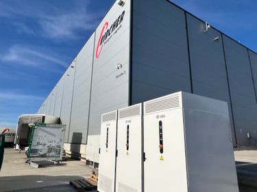
Ultimati Energie's Alheim logistics project shows why battery sizing must be based on charger intervals, not only installed charger power.
| Site element | Project value |
| Grid connection | 160 kW |
| Rooftop PV | 600 kWp |
| Truck chargers | 2 x 400 kW |
| Installed charging power | 800 kW |
| Battery system | 3 x ULTIBLOCK-TL261 |
| Total battery power | 375 kW |
| Total nominal battery capacity | 783 kWh |
If both chargers request full power, the gap between installed charger power and the grid connection is:
800 kW - 160 kW = 640 kW
The three battery cabinets cannot turn a 160 kW grid connection into a continuous 800 kW supply. That is not the right claim. The correct value is that the battery system can support short high-power intervals and make one 400 kW charging session practical under controlled conditions.
Without PV contribution:
160 kW grid + 375 kW battery = 535 kW
That can support one full-rate 400 kW charger before other site loads and losses. It cannot continuously support two 400 kW chargers at night.
With PV contribution, the operating window improves. If the rooftop PV contributes 300 kW at a given moment:
160 kW grid + 375 kW battery + 300 kW PV = 835 kW theoretical site supply
In practice, EMS control must still account for PV fluctuation, truck departure priority, battery state of charge, reserve limits, site loads and charger behaviour.
Where ULTIBLOCK-TL261 Fits
ULTIBLOCK-TL261 is relevant when the depot needs a modular C&I battery cabinet behind the meter, not a front-of-meter grid project.
For truck depot charging, the relevant product fit is:
- 261 kWh battery cabinet for short-duration charging support
- Liquid cooling for stable operation under repeated charge/discharge cycles
- IP55 design for demanding commercial environments
- 8,000+ cycle design life for daily C&I operation
- -20°C to 55°C operating temperature range
- System-level monitoring and protection for managed commercial sites
- The product should be positioned as a buffer for depot charging, PV self-consumption and peak management. It should not be described as a solution for large front-of-meter projects.
How to Decide How Many Cabinets Are Needed
Use a simple three-step method.
1. Model truck arrival windows
Depot charging is schedule-driven. A charger may be installed at 400 kW, but the battery only needs to support the real charging intervals.
| Question | Why it matters |
| How many trucks arrive together? | Determines simultaneous charger demand |
| How long is each stop? | Determines kWh discharge duration |
| Which trucks leave first? | Determines EMS priority |
| Can charging be sequenced? | Reduces battery power requirement |
2. Separate power from energy
Battery power answers: how much of the kW gap can the battery cover?
Battery capacity answers: how long can it keep doing that?
For one 400 kW charger with a 160 kW grid connection:
400 kW charger - 160 kW grid = 240 kW battery support
For a 45-minute session:
240 kW x 0.75 h = 180 kWh before losses and reserve
A 261 kWh cabinet may fit that single support window. If two trucks arrive close together, the design may require multiple cabinets, PV contribution, charger power limits or longer spacing between sessions.
3. Check recharge time
A battery-buffered depot fails if the battery cannot recharge before the next truck arrives.
Recharge time = Energy discharged / Available recharge power
If a charging event uses 180 kWh and only 90 kW is available for recharging after site loads:
180 kWh / 90 kW = 2 hours
This is why EMS scheduling matters. The system must decide when to recharge from PV, when to use spare grid capacity and when to reserve energy for the next priority truck.
What Funding Applicants Should Check Before Final Design
Before applying for or implementing truck charging infrastructure, a depot should collect:
- 15-minute site load data;
- available grid capacity and transformer rating;
- planned charger power and number of charging points;
- truck arrival and departure schedule;
- rooftop PV profile, if available;
- reserve requirements for operations;
- local grid operator requirements;
- installation space, fire protection and cable routing conditions.
Funding can reduce capital cost. It does not replace this sizing work.
Conclusion
Germany's 2026 electric truck charging funding creates a strong reason for logistics operators to move faster, but the decisive design question remains local: how much power can the site actually supply during each charging interval?
For grid-constrained depots, battery storage should be sized from the power gap and session duration:
Charger demand - grid capacity - usable PV = battery support power
ULTIBLOCK-TL261 is a good fit when the project needs a 261 kWh C&I battery cabinet to buffer charging peaks, use PV more effectively and reduce dependence on immediate grid reinforcement.
FAQ
Does Germany's truck charging funding include battery storage?
Funding rules should be checked against the official call documents. This article focuses on the technical sizing question: whether battery storage is needed when charger power exceeds available grid capacity.
Can one 261 kWh cabinet support a 400 kW truck charger?
It depends on grid contribution, charger duration, usable battery capacity, discharge limits and reserve settings. If the grid supplies 160 kW, the battery may need to support about 240 kW for a 400 kW session.
Why use battery storage for depot charging?
Battery storage can reduce short-duration grid peaks, store PV for charging windows and help a depot operate high-power chargers when the grid connection is limited.

Ultimati Energie Deutschland GmbH is a Germany-based B2B energy storage system provider specializing in scalable residential and C&I battery storage solutions for European partners.
Become a Partner
Sales: +49 1624886367
Customer Support:
+49 15226994869
Address: Ober der Röth 4, 65824 Schwalbach am Taunus, Germany
Copyright © 2026 Ultimati Energie Deutschland GmbH All rights reserved.